Close


Download
Computing the strenght of indexing plungers for shear loads / flexure loads of the plunger pin
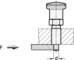
Shear loads
Provided that a miniscule gap remains between the guide of the indexing plunger and the indexing bore hole opposite, the load can be reduced to a clean shear action. As this is normally not the case, the “flexure” load case should preferably be considered on the following page. Approximately 80% of the bolt’s tensile strength is assumed for the shear strength. This approach calculates against the tensile strength Rm, i.e. against the indexing pin shearing off. Any pre-existing and remaining deformation may, however, mean that the indexing plunger can be used no longer. To ensure the permanent and proper function of the indexing plunger, the yield limit Re must be considered in place of the tensile strength Rm.
Formulas for computation
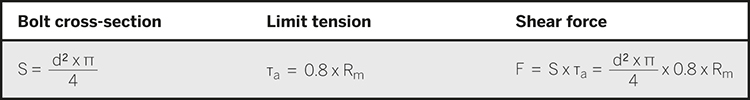
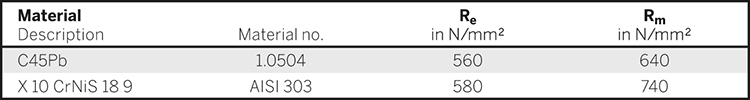
Material characteristics
The tensile strength shown in the table below (Rm) and the yield or substitute yield limit (Re / Rp 0.2) have been determine in tension tests involving tension specimen in accordance with DIN 50125-B6-30. These tests constitute the basis for the load bearing details given herein.
Computing examples, load values
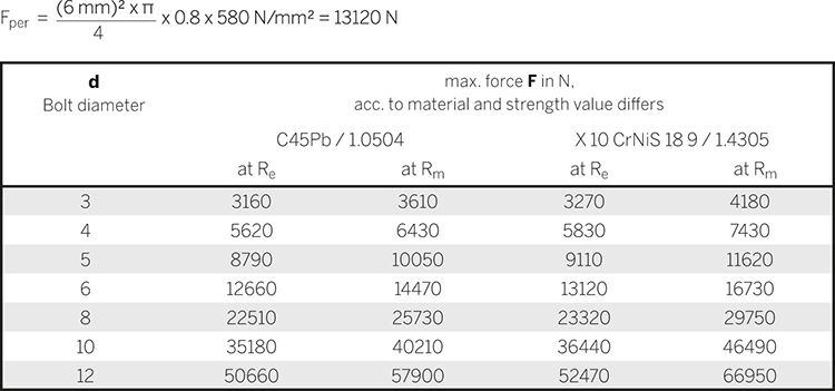
Example:
Indexing plungers with a bolt diameter of 6 mm made of Stainless Steel with a yield limit of Re = 580 N/mm2, computation against permanent deformation, the maximum permissible shear stress is wanted.
Safety information
On principle, the design also needs an adequate safety coefficient to be taken into account. The usual safety coefficients under static load 1.2 to 1.5; pulsating 1.8 to 2.4 and alternating 3 to 4.
Disclaimer:
Our information and recommendations are given with non-binding effect and ruling out any liability, unless we have expressly committed ourselves in writing to provide information and recommendations. All products are standard elements for versatile uses and as such are subject to extensive standard tests. You should carry out your own test series to verify whether a certain product is suitable for your specific applications. We cannot be held responsible for this.
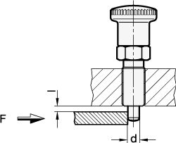
Flexure loads
As soon as a gap I remains between the guide and the indexing bore hole opposite, the load can be reduced to a flexure rod clamped in at one side.
With this approach, the computation is made against the bending of the indexing plunger as a case of failure.
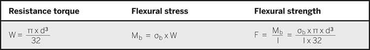
Formulas for computation
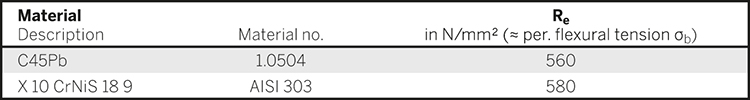
Material characteristics
The yield or substitute yield limit (Re / Rp 0.2) shown in the table below has been determine in tension tests involving tension specimen in accordance with DIN 50125-B6-30. These tests constitute the basis for the load bearing details given herein.
Computing examples, load values
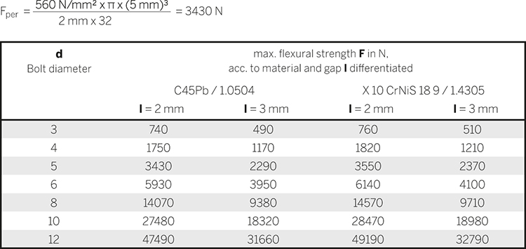
Example:
Indexing plungers with a bolt diameter of 5 mm made of steel with a yield limit of Re = 560 N/mm2, computation against permanent deformation, the maximum permissible flexural strength is wanted:
Safety information
On principle, the design also needs an adequate safety coefficient to be taken into account. The usual safety coefficients under static load 1.2 to 1.5; pulsating 1.8 to 2.4 and alternating 3 to 4.
Disclaimer:
Our information and recommendations are given with non-binding effect and ruling out any liability, unless we have expressly committed ourselves in writing to provide information and recommendations. All products are standard elements for versatile uses and as such are subject to extensive standard tests. You should carry out your own test series to verify whether a certain product is suitable for your specific applications. We cannot be held responsible for this.